 MT50e Walk-Around
 Download PDF
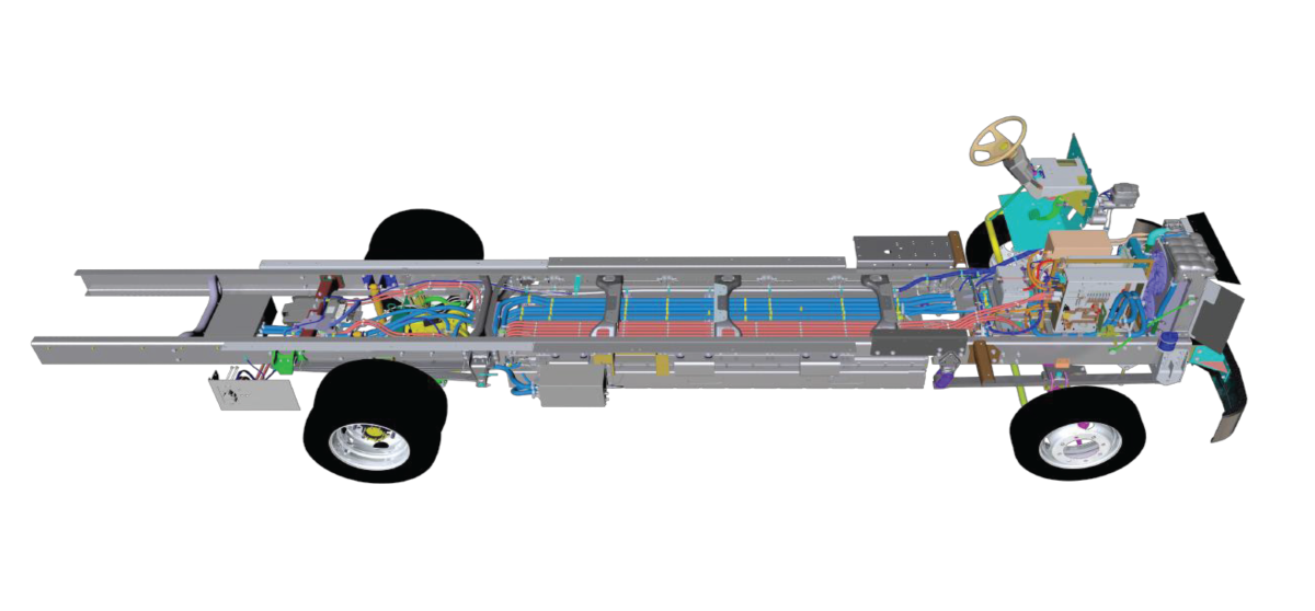
Chassis High Voltage Component Layout
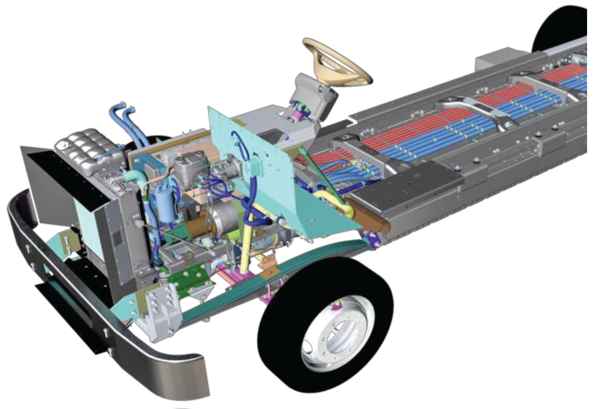
Front Box Compartment
High Voltage Junction Box (HVJB)
Controls the connections between the HV batteries, charging input, drivetrain/inverter, ancillary HV loads, DC/DC and DC/AC converter, and AC Variable Frequency Drive (VFD). Includes a HV Cut-Off Switch loc ated on the front end with Lock Out - Tag Out Tab
Power Steering Pump & Motor
Baldor Reliance High Voltage Motor with Eaton Power Steering Pump 3 Phase 5 HP (3.7kw – 208-230v) electric motor Activated when: Vehicle Speed Detected / Parking Brake is Released / Drive Mode is Selected Same steering gear as on other MT products
Variable Frequency Drive (VFD)
2 VFD’s that acts like an alternator Upper VFD controls current for AC Compressor and Power Steering Pump Lower VFD Controls current for LV (12v) batteries and body
accessories
Radiator
Same radiator used in all MT products
Uses the same coolant for the batteries and cabin heaters OAT 50/50 Coolant
Telematics
Vehicle Monitoring – Real-Time information and vehicle performance
Remote Diagnostics – Reduce on-site visits and solve problems remotely Preventative Maintenance – Notifications and
Recommendations Charger Management – Monitor Charger Status Remotely and Receive Updates
A/C Compressor
A/C compressor provides cooling for batteries through the Battery Thermal
System (BTMS)
Chassis option for body A/C connection standard on MT50e, driver dash option available from body builder
Electric Vehicle Alert System
Sound Generator are mounted front left side in the bumper and behind rear bumper with the backing alarm. Meets all FM VSS Certifications.
J1939 CAN Compliant. Sound will generate from 1mph to 20mph
High Voltage Heaters
2 HV Heaters mounted under the front engine compartment 20kW heater produces heat for the batteries
20kW heater produces heat for the cabin area
Low Voltage Batteries
1 – 12v AGM Low voltages located in the battery box compartment area, under dog house
High Density Batteries
Low Voltage Cut-Off Switch
LV Cut-Off switch located in the battery box compartment area, under dog house with lock-out tag-out
Switch has to be in the “ON” Position to activate charging of batteries
When switch is in the “OFF” Position, High Voltage cannot be activated.
Warning: Do not switch to “OFF” when vehicle is in High Voltage
Mid-Ship Chassis
Coolant Lines
Stainless steel coolant tubing lines are routed above battery packs
Inside of chassis frame rails
High Voltage Cables
ALL HV Cables are Orange with convoluted
covering
Consist of copper conductor sized for load,
braided shield and High Voltage Interlock Loop
Cross Members
Additional cross members added to help support: HV & Coolant Lines. Each cable
and hose are tied down individually to eliminate hazards.
High Voltage Proterra Batteries
(2) 123kW Batteries – 246kW Total Capacity –Optional (2) 82kW Batteries – 164 kW
Total Capacity - 90% useable capacity. Useable Capacity reduced to manage
battery degradation. Packs Protected by 10 mm aluminum ballistic grade material.
Each battery has its own (MSD) Manual Safety Disconnect on the street side
“identified in orange”
eAxle
Dana eS9000r e-axle all electric drive technology; 318 HP (237 kW)
Motor Controller / Invertor
Power flow through the inverter is bidirectional. When accelerating, DC Power is
converted to AC Power to propel the truck forward and reverse. When decelerating,
the AC power is converted back to DC Power and recharges the main batteries.
Battery Thermal Management System (BTMS) Coolant
BTMS in electric vehicles is critical for maintaining energy storage capacity, driving
range, and cell longevity and system safety.
Batteries optimal performance temperature is around 70 degrees.
Aft of Rear Axle
eAxle Inverter
eAxle inverter is located between frame rails for increased safety protection Inverter converts battery, DC power to AC power for eAxle
Charge Port
Standard CP is located curbside behind the rear axle.
Red & Green Light Indicators with Stop Charge Button
Requires a J1772 CCS Type 1 Connector.
DC Charging is standard, Optional DC/AC charging is available.
Optional AC onboard charger (OBC)
AC onboard charging, maximum charging is 19.2kw
Inside Cabin Area
Drivers Instrument Cluster
Digital Optiview dash interface.
Hydraulic Park Brake
Hydraulic part brake is located left of driver column
Park brake must be fully dis-engaged for vehicle to operate
Cable tension adjustment knob located on tip of lever
Hill-Start Assist
It is a device that holds the vehicle on any Up or Down Grade for up to 4 seconds.
Hill Hold Assist works by holding the service brake while the driver is moving their foot from the service brake pedal to the accelerator pedal to prevent the bus from rolling forward or backwards while on a grade.
Regenerative Braking
Regen works by acting as a brake on the EV Bus as soon as the driver lifts their foot off the accelerator.
Allows the electric vehicle to reuse the energy generated by slowing down
through battery storage.
Regenerative Braking “ON” position is right-hand stalk switch in the “UP” position,
regenerative braking “OFF” is right-hand stalk switch in the “DOWN” position
Regenerative braking ON/OFF displayed in driver dash
Regenerative braking inhibited above 90% SOC